What is a linear position sensor?

What is a linear position sensor?

They are all around us – in our car suspension systems as we drive over speed bumps, in the trains we sit in as they move around curved tracks and in the ‘fly-by-wire’ aircraft that adjust their ailerons and elevators as they start to descend. They are in the factory machines that we work with every day to package and manufacture products, and in medical equipment that keeps us alive. What are these inconspicuous but crucial devices? They are linear position sensors which are helping to embed digital technologies in the next industrial revolution.

Linear position sensors and custom electronic circuitry

Linear position sensors measure the linear distance between an object and a point of reference, as well as speed and changes in position. They do this by converting linear displacement into an extra low voltage, in either an analog or digital signal. That electrical output is generated by exploiting different phenomena in nature such as magnetic fields, solar energy and electrical resistance. Excitation circuitry in the sensor creates a stimulus and signal conditioning circuitry then selects and amplifies the electrical response. Sensors then digitise the signal using an Analogue-to-Digital Converter (ADC), the digital result is then passed to a Central Processing Unit (CPU).

The Fourth Industrial Revolution

The Fourth Industrial Revolution or Industry 4.0 is well underway and adopting next generation linear position sensors that employ Application Specific Integrated Circuits (ASICs) to deliver the speed, accuracy and cost savings to industrial automation. Linear position sensors detect the location of machinery and equipment parts so they can be tracked and automated. They provide a digital signal via Ethernet connectivity to accurately report the target position in real-time with sufficient resolution. Sensor electronics are a key part of the evolution in automation, having direct influence on speed, accuracy and overall form factor.

What are the basic types of linear position sensor?

Linear position sensors consist primarily of two types: contact and non-contact, depending on whether they require physical contact to measure. Contact sensors tend to wear or degrade over time due to the constant friction for example of the wiper in a linear potentiometer measuring electrical resistance. In contrast, noncontact sensors use magnetic fields, solar energy and lasers to sense changes in position so they are less prone to wear and tear and can tolerate higher levels of vibration.

Linear encoders

A linear encoder is a sensor, transducer or readhead combined with a scale that encodes position. The sensor moves along the scale which it ‘sees’ using optical, magnetic, inductive, capacitive or eddy current technologies. It then converts the encoded position into an analog or digital signal, which is then decoded into position by a digital readout (DRO) or motion controller.

A linear encoder can be either incremental or absolute. What does this mean? Incremental encoders use a simpler method of determining movement by counting the number of pulses and then using that number to compute the position. With an absolute encoder, the output signal generated by the device creates a unique set of digital bits that correspond to a specific position of the object being measured. So incremental encoders measure the relative movement against some point of reference, whereas absolute encoders measure the position directly using a unique signal code that precisely reflects the position.

Linear encoders are used in two main areas of application: measurement and motion systems.

Measurement applications include coordinate-measuring machines (CMM), laser scanners, callipers, gear measurement, tension testers, and digital readouts (DROs).

Servo controlled motion systems provide accurate, high-speed movement in robotics, machine tools, pick-and-place PCB assembly equipment, semiconductors handling and test equipment, wire bonders, printers and digital presses. Humans design these intricate circuit boards but cannot match the speed and accuracy of robots and assembly equipment.

Linear potentiometers

In a linear potentiometer a wiper moves along a resistor as the equipment moves through the full length of stroke, providing a variable resistance related directly to position. Signal conditioners then convert this reading into other electrical output levels. Linear potentiometers are a tried and tested sensing method that are simple, inexpensive, and easy to work with. Although they are a fundamental method for detecting equipment position, as a physical device subject to constant mechanical wear they deteriorate over time and need to be replaced. They may not be resistant to liquids and contaminants, and the form factor must be large enough to accommodate the fully extended and retracted rod stroke, which can be limited in use due to installation space constraints.

Linear potentiometers can measure spring travel in bicycles and motorcycles so as to determine the optimal spring fork for challenging terrains, especially in motorsports. Imagine a mountain biker in Utah, USA speeding through wooded forests, Aspen Pine lands, bubbling streams and then across open prairie land, bouncing easily off paths covered with roots and stones thanks to the valuable data these sensors provide in the design of mountain bikes.

Aside from sport, more mundane but crucial applications include agricultural machinery, increasingly automated, moving across vast open fields. Lumbering combine harvesters use linear potentiometers for the wheel angle measurement in their steering systems as they move back and forth.

Linear potentiometers can also measure the stroke movement of both hydraulic and pneumatic cylinders by installing them directly inside the cylinder itself. The sensor compares the target stroke with the actual stroke to ensure process safety. Reliable measurement data is collected even at high pressure.

Being one of the most versatile and widely used sensors in industry, linear potentiometers are used in a whole range of applications including the control of motors and actuators, robotics, industrial machines, audio equipment volume control, automotive engine control systems, calibration for precision test equipment and medical equipment.

Hall effect sensors

A Hall effect sensor detects the presence and magnitude of a magnetic field using the Hall effect: namely when a conductor flowing with electrical current is plunged into a perpendicular magnetic field a voltage (the Hall voltage) is generated. It was discovered by the American physicist Edwin Hall in 1879. The output voltage of a Hall sensor is directly proportional to the strength of the magnetic field. Exploiting Hall Effect technology enables the sensors to be non-contact resulting in highly precise measurements and an exceptionally long mechanical life.

Hall sensors are used in proximity sensing, positioning, speed detection, and current sensing applications. Combined with threshold detection a Hall Effect Sensor can act as a binary switch. Frequently seen in industrial applications such as pneumatic cylinders, they are also used in consumer equipment for example detecting missing paper and open covers in computer printers. They can also measure filament thickness in the 3D printers as used in rapid prototyping, among other things.

Hall sensors time the speed of wheels and shafts in internal combustion engine ignition timing, tachometers and anti-lock braking systems and detect the position of the permanent magnet in brushless DC electric motors.

How can Live Electronics support manufacturers with linear position sensors?

Here at Live Electronics we are continually looking for the best products at the best price to help with modern technologies such as linear position sensors. Our linear position sensors from ZF use Hall Effect technology which allows the sensors to be non-contact resulting in highly precise measurements and an exceptionally long mechanical life.

FAQ's

What is a linear position sensor?

Linear position sensors measure the linear distance between an object and a point of reference, as well as changes in position. They are used for detecting the location of machinery and equipment parts so they can be tracked and automated.

How does a linear position sensor work?

Linear position sensors exploit different phenomena in nature such as magnetic fields, solar energy and electrical resistance to convert the displacement of moving machinery into an electrical output.

How many types of linear position sensors are there?

There are many types of linear position sensor, however the linear potentiometer is widespread being an inexpensive and easy to use piece of equipment. The Hall effect sensor however is becoming the most common due to its non-contact nature, resulting in highly precise measurements and an exceptionally long mechanical life.

How do you test a linear position sensor?

A linear potentiometer can be tested using a voltmeter. With a linear potentiometer fully extended, the voltmeter should display the maximum volts of the sensor in DC. With the linear potentiometer fully retracted, the voltmeter should display zero volts DC. The Hall effect sensor can be tested in a similar way in that the voltage changes from 0V to 5V (the high voltage can be changed based on the set up but usually this is between 1-5V, with 5V being the most common)


What is an RJ45 connector?

Origins in telephony

Long before the world wide web came into existence and local area networks for computers had spread around the world, many if not most people in the USA didn’t even have a telephone at home and those who did just leased it from the Bell Company. The telephone network was still in its infancy in America, starting in the 1870s and steadily becoming more common by the 1940s. It owned not just the normally black and bulky telephones and handsets but all the wires on the poles, the switchgear in the central offices and the microwave links too. They had complete control over every aspect of their service delivery, and used their monopoly to build an amazingly integrated and durable system.

But there was a problem. And a big one. With all this power came responsibility and if anything went wrong with the customer’s phone it was Bell who had to fix it. A little boy in a moment of innocent curiosity once cut the handset cord with a pair of scissors. A technician from Bell had to come out and take the phone apart as well as the wall connection just to install a new handset cord. This was no quick replacement. Another time a dog chewed the cord between the set and the wall. Another technician was sent out on a mission. And this repeated over the entire network – all manner of unfortunate events. Even with no curious toddler or beloved pet, the phone cord would eventually fray and break, never mind if the bulky phone was designed to last for 40 years or more. What could be done to stop the phone company sinking ever more money into customer service calls?

A modular family was born

It was the late 1960s and AT&T was now on the scene. It ordered its engineers at Western Electric, its manufacturing arm, to focus their brilliant minds on the problem. The team, including Edwin Hardesty and Charles Krumreich eventually came up with the solution: a rectangular moulded plastic connector that had multiple parallel conductors, plastic channels to isolate and insulate each circuit, insulation displacement contacts in the plug, and springy wire contacts in the socket. A later design would replace the spring wire contacts in the socket with fixed blades.

Focusing on insulation displacement meant that field technicians could now mass terminate the connector with a simple crimp tool. The connectors were also easier to manufacture in the huge numbers required for a system-wide conversion. Moulding the plug body also meant that strain relief could be integrated into the plug, in the form of a flexible bar that would be crimped down onto the cord jacket after the electrical connections were made.

The design would be modified yet again, returning to spring wire contacts in the socket and replacing the original metal latch that locked the plug into the socket with a moulded plastic latch. But the basic design of the modular plug was now determined and ready for the future. The Trimline phone, where the handset now contained the dial or keypad, was one of the first phones to use the new connectors and throughout the 1970s, a decade of both cultural change and technological innovation, phone companies across the country retrofitted millions of existing phones.

In the 1980s the powerful AT&T monopoly began to break up and the new modular connectors now played an important role in democratising the entire phone system. For the first time customers could go into a store and buy whatever colour or style of phone they wanted, rather than leasing as before. One housewife went out and bought a new phone while her husband was at work. When he arrived home she had managed to rewire the new RJ11 connector into the wall using a special DIY kit promoted by AT&T.

Intuitive design, easy extensibility to more or fewer conductors, and the saturation of the market thanks to a large installed customer base all led to the modular connector being accepted across a wide range of industries. In 1976 the Federal Communications Commission mandated that phone system connections be standardised for interoperability so that customers could finally connect their own equipment to the telephone network.

The mandate termed these specifications registration interfaces, and the modular connectors became known as registered jacks, or RJ for short. The RJ11 became the connector for plugging a telephone into the wall and the handset into the telephone, while the RJ14 was designed for connecting multiple lines leading to a single phone unit. Crucially, an eight-conductor modular connector eventually became the standard for Ethernet connections. This was the RJ45. Its original 8P2C modular connectors were later modified into an 8P8C configuration with an additional tab or latch to ensure correct orientation in the newly arriving ethernet local area network (LAN) revolution.

An imaginary, networked world quietly in the making

The years passed and in 1995 at the dawn of The Internet, Mirek, the owner of a small computer software and network installation company in south-west Poland was going to change the world. In his office or inner throne room he plotted the expansion of his business. Across the grey carpeted floor a black telescope goldfish with bulging, distended eyes swam lazily in its bowl. It matched the black wall unit the bowl rested on. A wall clock ticked over a low glass coffee table, near two black leather sofas. Outside a sign fixed to the building showed the bright logo of his company accompanied by a globe encircled by parabolic connections. Giant cables soaring from the ground into space would enter the Earth at some point and then shoot off again to some other distant location, making a connection. This repeated many times. This crude but fantastical vision depicted a future networked world, using gargantuan cables. This was long before WIFI had become omnipresent or even thought of.

The vision came true

By 2005 the young entrepreneur had long left Poland for Chicago to pursue his career and dreams far away in the USA. His offices had been taken over by another company but that sign still hung outside on the building, waiting to be taken down. Now faded, the networked world could barely be seen. But those imaginary space cables had in fact gone on to envelop the world with countless terrestrial networks of interconnected computers all thanks to that original future proofed connector developed years earlier in a different technological age. Remember that years in the technological sphere are comparable to decades if not centuries in other domains.

Simple, adaptable and backwards compatible

The RJ45 consisted of both a male connector or plug attached to an ethernet cable and a matching female jack or port normally built into the back of a desktop computer or other internet enabled device. The magic of the RJ45 was its ability to be re-invented to support ever increasing data rates as well as be backwards compatible. Standardised in 1987, billions of these connectors have gone on to link up the world. Nowadays business people and travel bloggers travel the world with their laptops and can plug these into any hotel ethernet port that is available thanks to the ubiquity of the RJ45.

There are other factors that resulted in the success of the RJ45 connector. These include the low cost, solderless assembly of connector and wiring which enables fast production of custom cables, simple insertion and removal, easy field assembly using simple crimping tools, and the ability to customise cables on-site. Sockets or ethernet ports can also be orientated vertically or horizontally increasing their functionality. RJ45 connectors also feature an orientation tab or retaining latch to prevent incorrect wiring. Their 8-pin configuration also means that they can be used in more demanding and data-intensive applications.

The inner workings of the RJ45

Even if we haven’t wired, crimped and terminated, most of us have at some point plugged an RJ45 plug into the matching jack or ethernet port in our modem, router, PC or TV set top box at home, hearing it snap into place. It consists of a plastic housing, often transparent but can be opaque and coloured too.

Inside every RJ45 are eight channels containing gold plated contacts separated by insulating plastic as well as a gold plated contact pin with either two or three prongs. These prongs “bite” into the individual wires when you press down on the RJ45 with a crimping tool. Piercing the wire insulation and connecting with the conductor is a mechanism known as insulation displacement. 3 prong connectors will work with stranded and solid copper conductors whereas 2 prong connectors work with stranded copper only.

The eight colour-coded wires are unravelled from the four twisted pairs of the ethernet cable and gently pushed through the separate channels of the RJ45 plug, then bonded to the gold contacts with the crimping tool. T568A and T568B are two wiring schemes that are used to connect the cable to the RJ45 connector interface. T568A is generally considered a superior configuration as it offers wider backwards compatibility. However, T568B is more common, especially in older cables and equipment. The correct standard will depend on whether a straight-through cable (often called a patch cable) or a crossover cable is required. In most cases a patch cable will be used, which has the same type of wiring standard at each end. Crossover cable is much less common with a T568A connection at one end and a T568B connection at the other.

When the RJ45 is pushed into the ethernet port the male and female contacts connect with each other as the tab locks the plug tightly into place. Data and signals then begin to flow back and forth along the ethernet cable, delivering web pages from the distant servers and emails from the local computer operator as well as a plethora of other information.

Newer variants and challenging environments

There are now four common types of RJ45 connector: standard, staggered, shielded and ruggedized.

Standard RJ45 connectors have eight pins or contacts that are arranged side by side in a straight line and designed for CAT 5 ethernet cables.

Staggered versions are meant for the thicker wires of CAT 6 cables. The larger channels and holes for the wires wouldn’t fit inside the modular size of an RJ45 if placed side by side as in the standard version.

Shielded RJ45 connectors are encased in shiny metal plating to cancel or protect from the effects of EMI/RFI. They are used in longer cable runs and factory floors where the effects of EMI/RFI are more pronounced from noisy machines and other sources.

Away from the home or office and in more hostile and industrial environments, field RJ45 connectors are more robust with ruggedised housing and sealed to IP67 or higher ratings to render them waterproof. Here they find applications in industrial control panels, machine automation, portable testing and measurement equipment as well as robust computing devices. An IP67 rated RJ45 can be temporarily submerged in water while IP68 allows permanent submersion and IP69K will give protection from high pressure water jets used during for example equipment washdowns.

Category 7 cables can be terminated with RJ45 connectors, but these are specialised versions called GigaGate45 (GG45). GG45 connectors are however backward compatible with RJ45 connectors.

Conclusion

In summary the RJ45 connector enables stable and secure data transfer between devices and machines where wireless signals are not an option in certain environments or simply unavailable. It is also worth noting that even wireless routers or modems still need to be plugged into the network via a RJ45 connector so an ethernet cable is never far away at home or the office.

How can Live Electronics support users of dedicated RJ45 connectors?

Here at Live Electronics we are continually looking for the best products at the best price to help with modern technologies such as ruggerised and waterproof RJ45 connectors.

FAQ's

What is an RJ45 connector used for?

An RJ45 connector is primarily used to connect computers and other devices to a local area network (LAN) or The Internet, especially if a more stable and secure connection is needed.

Are there different types of RJ45 connectors?

The different types of RJ45 connector available, depending upon the application include:

Standard – 8P8C (8 position, 8 connection), non-shielded.

Shielded from EMI/RFI.  – internally shielded connectors that incorporate a shielding plate. May also be termed RJ48.

Ruggedized – include various external parts to protect the device from harsh environments.

RJ45 connectors can also be 2 prong or 3 prong. 3 prong connectors will work with stranded and solid copper conductors whereas 2 prong plugs work with stranded copper only.

Is an RJ45 port the same as an ethernet port?

In short, the answer is yes. The RJ45 port is the network port on a computer. This socket is also known as the Ethernet port, the network adapter, the network jack or the RJ45 jack.

Are RJ45 connectors the same for CAT5 and CAT6?

No, Cat 5 or more commonly Cat5e connectors have a straight pin layout whereas Cat6 connectors have a staggered pin layout. This is because the staggered layout is beneficial in reducing cross-talk interference. In conjunction with the design of Cat6 cable, this enables higher data transfer speeds of max 10Gbps up to 55 metres compared with 1Gbps at 100m for Cat5e.

How does an RJ45 connector work?

RJ45 connectors feature eight pins to which the wire strands of a cable interface electrically. Each connector has eight locations spaced about 1 mm apart into which individual wires are inserted using special cable crimping tools. When the RJ45 connector is plugged into the ethernet port data begins to flow back and forth bringing the screens and devices to life.

How do you plug in an RJ45 connector?

The male connector or plug of the RJ45 is pushed into the female socket or jack, also known as the Ethernet port, the network adapter, the network jack or the RJ45 jack. RJ45 connectors are designed with a latching mechanism that secures the physical connection. As the connector is inserted into the socket, a plastic tab on the connector locks against a ridge in the socket so that the plug cannot be removed without disengaging the tab by pressing it against the connector body.

What is a Circular Connector?

What is a Circular Connector?

A circular connector is composed of two parts – a cylindrical, multi-pin male plug and female receptacle with corresponding sockets that when mated with each other is designed to power electrical devices or transmit electrical signals. Their circular design is effective in withstanding harsh environments and can reliably deliver both data and power. From the International Space Station moving at 7.66 km/s around the Earth, astronauts looking through its cupola at the continents down below, to fighter jets and passenger aircraft flying high above the clouds, to nuclear powered submarines that lurk in the icy depths of the arctic ocean and subsea internet cables that trail across ocean floors, circular connectors deliver crucial electrical signals and power to massive machines operating in harsh environments that must be fail safe and dependable.

Enabling A Central Nervous System For Machines

These circular connectors and cables act like the nerves and blood vessels that deliver feeling and strength to our bodies. They are like nodes in the central nervous systems of aircraft, wind turbines, tidal turbines, expansive solar farms, marine vessels, trucks and trains. These cannot afford to fail in the harsh environments that they operate, otherwise catastrophe awaits. They are ‘fit and forget’ technology that can be relied on to perform their function whether underwater, pounded by wind, waves and vibrations or exposed to extreme pressures, the freezing cold or searing heat. But aside from space stations, fighter jets and large passenger planes, submersibles moving slowly in the dark and deep-sea mining robots lumbering across ocean floors in the search for rare earth minerals for our phones and EVs, most circular connectors are used in the vast array of factories and industries on land that deliver the power, data, warmth, food and products that we so desperately need. But what are circular connectors actually made up of?

Shells, Inserts, Contacts And Backshells

Circular connectors as judged by their name consist of two circular parts, a multi-pin male plug and a multi-socket female receptacle. In the male plug a circular shell made from plastic or metal encases an insulating insert which in turn orientates electrical contacts or pins. The female receptacle contains the corresponding sockets that the pins mate or connect with. The shell diameters range in size from nanominiature circular shells a few millimetres across to those 50 mm in diameter or more. Larger shell sizes are generally used to house larger contacts used for power or more contacts whereas smaller shells are designed to house the smaller contacts needed for sensors.


The cylindrical housing and circular contact interface geometries allow for easier engagement and disengagement, tight environmental sealing, and rugged mechanical performance. The male plug of the connector containing the pins plugs into the female receptacle containing the sockets. They are especially resistant to environmental interference and accidental decoupling through the use of screw, bayonet, twist-lock and push-pull mating styles and can be sealed to IP67 or higher.


When the male plug and female receptacle are pushed together and make contact electrical current flows through the electrical contacts that are made from high-conductivity, oxidation-resistant materials like brass and steel. These can be bare or plated in gold and/or silver to offer better conductivity for lower voltages and currents. They are usually attached to each wire strand within the cable using solder or screw fittings or by using a crimping tool, which employs a solderless crimp mechanism. Each contact is passed through the circular connector housing and insert before the connector backshell is closed. In the case of a crimp fitting individual contacts can be replaced without requiring the entire connector having to be replaced.


Circular connectors commonly use backshells, which provide physical and electromagnetic protection as well as also providing a method for locking the connector into a receptacle which provides stress relief for the attached cable. In some cases this backshell provides a hermetic seal or some degree of ingress protection. As well as protecting the multi pin circular connector and cable link from physical stress like strain, shock or vibration, backshells can also stop any electromagnetic interference that can occur when lightning strikes an aircraft or wind turbine tower. Backshells are also known as endbells, strain-relief clamps or cable clamps.

Mounting

Circular connectors are designed to mount in-line on a cable end or directly to panels, circuit boards or other entry points. There are several methods for affixing the connector including the use of bulkheads, jam nuts and flange mounts. The two most widely used circular connector mounting types are jam nuts and flange mounts. A jam nut uses a large hex nut to screw onto the connector’s threads and is used in applications with space constraints. A flange mount has a protruding ridge, lip or rim that is bolted onto panels or other entry points that serves to increase strength.

Hybrids And Medical Environments

In medical environments where crucial life support systems and ventilators are connected up to patients, time cannot be wasted in searching for the correct cable in the event of a medical device misconnection in complicated systems. Hybrid connectors are the perfect solution to this predicament as they can connect high voltages, optical links, fluids, power and signal lines through a single connector. Hybrid connectors often consist of a rectangular plug that itself contains several circular connectors which enables clinicians to connect complex medical equipment efficiently and quickly. Keyed circular connectors with different colours and sizes can also make it impossible to connect the wrong cable.

The Circular Enablers of The Industrial Internet Of Things

Circular connectors come in a range of shell sizes but the rugged and durable M12 connectors have a long history of use in industry long before The Internet was a thing. However now that The Fourth Industrial Revolution (Industry 4.0) or the Industrial Internet of Things (IIoT) is currently underway they have become the preferred connector for Industrial Ethernet. Designers and original equipment manufacturers (OEMs) are incorporating M12 connectors into new machines as industrial environments become ever more connected. They are also using these connectors to update existing infrastructure. Using M12s to replace older and less robust technology is relatively simple and cost-effective because of their backward compatibility.

How can Live Electronics support different industries with circular connectors ?

Here at Live Electronics we are continually looking for the best products at the best price to help with modern technologies such as circular connectors. We supply IP68 rated waterproof, highly robust and high voltage/current connectors all the way down to 6mm low voltage connectors. Different mating styles range from screw and twist-lock to bayonet and push-pull. We also supply hybrid connectors which are ideal for connecting both power and signal circuits through a single connector. With many different choices available please feel free to contact us to discuss your requirements, we are always happy to help.

FAQ's

What does a circular connector do?

A circular connector provides a robust and failsafe connection to supply electrical signals, data and power. Circular power, data, fibre and automation connectors are used in a range of demanding environments both on land and at sea.


Where are circular connectors used?

Circular connectors are used in critical areas such as the military, aerospace, hospitals as well as hostile environments. In industry they are used in test, measurement and automation technology. They are also used in sound engineering and radio communication. In 5G mobile communications they are used to connect Antenna Line Devices or ALDs

What are circular connectors made of?

The shell of a circular connector is made from plastic, metal or moulded rubber and the insert from a moulded piece of resilient dielectric material. The contacts are made from high-conductivity, oxidation-resistant materials like brass and steel. These can be bare or plated in gold and/or silver to offer better conductivity for lower voltages and currents.

Electric vehicles (EVs) are already here and fast becoming the future of transportation

How and why will EVs be the main vehicles in the future?

Just like the internet and then the smartphone, electric cars will soon be a mainstream product that most of us never had and yet in the course of our lives changed everything beyond recognition.

This revolution is being accelerated not just by the natural growth of technology but also the grave danger that faces humanity and nature: namely global warming and climate change. Humanity’s back is against the wall. Which in reality is a great motivator and innovator.

Within transportation cars are the biggest source of greenhouse gases and electrifying them will go a long way towards halting the destruction to the thin layer of atmosphere that separates us from the dark void of space. Fuel cell EVs that use hydrogen as the fuel source instead of a battery are also another option that could make headway. We have no choice but to give up fossil fuels – and fast.

Even if the electricity grids that power electric cars are fed by fossil fuels this is still better for the environment as EVs are more efficient at converting energy to power in addition to being emission free. They are cheaper, cleaner and perfectly adequate for home charging and the local area. Until longer lasting solid state batteries arrive on the scene and the charging networks have been fully built, the worry about having enough range to reach one’s destination will remain an issue but with good planning this can be avoided.

Automakers are scrambling for position in the new gold rush, eager to capture positions of dominance in this new industry. Tesla has been the leading innovator so far with the manic genius of Elon Musk at the helm, but others are close behind including established German automakers and one of the richest tech titans on the planet: Apple.

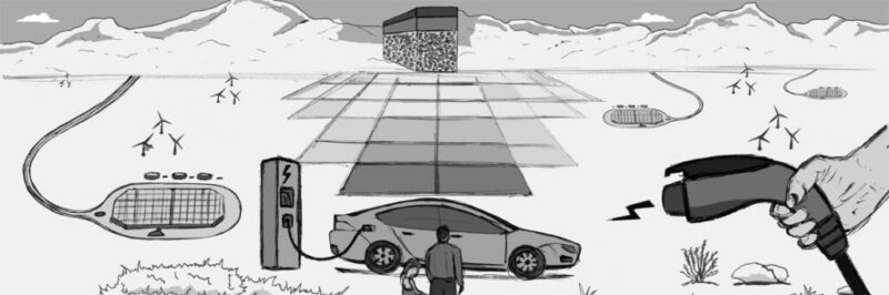
So far ‘halo vehicles’ like those from Tesla have been built for wealthy early adopters but ultimately products for the mainstream consumer will need to be mass produced. Gigafactories providing thousands of new jobs are being built on different continents to manufacture the powerful batteries needed to drive this revolution forward to achieve a zero-carbon future. Resembling gargantuan battery packs lying flat on the landscape, with access roads coming off them like attached cables, these huge factories manufacture not only batteries but the electric motors that make up part of an EV.

But all this comes at a price and as always there are winners and losers. The natural environment is being poisoned and destroyed in the hunt for the lithium and cobalt metals needed to make the essential batteries come to life. As production ramps up remote communities will be starved of their local drinking water, needed in huge quantities in the bright yellow and green lithium evaporation ponds covering the landscape in Chile’s Atacama salt flat.

Even this is only the beginning, just a trickle before demand for EVs turns into a raging torrent. Can the earth keep up with the demand? For even these metals are finite and non-renewable. Alternatives will have to be found and research is already underway.

What types of EV are currently available?

All types of vehicle will eventually become electric including cars, vans, buses, garbage trucks, HGVs or trains. City bus fleets are some of the earliest being converted to electric. The main focus is currently on cars though, as that is where the biggest difference will be felt in terms of greenhouse gas emissions and poisonous smog in our cities. Three different technologies exist:

Battery electric vehicles or BEVs – also called an all electric vehicle – this runs entirely on a battery and electric drivetrain, the electricity being stored in a large battery pack which is charged by plugging into the electricity grid. These are the future of EVs, the next step in evolution from so-called “hybrids”.

Plug-in hybrids or PHEVs – has both a petrol or diesel internal combustion engine along with an electric motor and large rechargeable battery which kicks in when the main IC engine is not being used. These are on the way out but were the first vehicles to use at least partial electricity.

Fuel cell electric vehicles or FCEVs – also known as zero emission vehicles. These split electrons from hydrogen molecules to produce electricity to run the motor. With this vehicle one would still fill up like at a regular petrol station, but with hydrogen under pressure. The only emission from the exhaust pipe is pure water. Despite ‘hydrogen highways’ being long in the making the main infrastructure being rolled out at present is for BEVs. The ‘hydrogen hype’ is in danger of being left behind or used in other industries.

Lithium-ion batteries

What are EVs, when it comes down to it? Giant batteries on wheels? EV car batteries after all work on the same technology as the lithium-ion (Li-ion) batteries that most of us carry around inside our mobile phones.

However, EVs don’t use a single battery like a phone, but instead a pack which is composed of thousands of individual Li-ion cells working together. When the vehicle is being charged, electricity is used to make chemical changes inside the batteries. When driving, these changes are reversed to produce electricity and the batteries are discharged. Just like with a mobile phone, repeated charging and discharging of the battery will eventually lead to it being able to store less energy. The time to fully charge will decrease between journeys, but so will the range. EV batteries are predicted to last anywhere between 10-20 years before they need to be replaced. This has not yet come about as fully electric vehicles have not been on the roads long enough, but because the greatest cost of an EV is the battery pack itself it is likely that people will just replace their entire cars and the battery will go on to be recycled or used in domestic or business energy storage systems.

Are solid state batteries the future?

Solid state batteries offer the possibility of giving at least twice the energy of lithium-ion batteries by using a denser solid electrolyte instead of one in a liquid state, as well as being safer and less prone to fire risk. The technology is still being worked on with the main problem being the price of manufacturing them. They are unlikely to be commercially viable until 2030 at the earliest and other technologies like hydrogen fuel cells may jump ahead by then. A major disruption in battery chemistry will need to occur for the cost of EVs to drop enough to become an integral part of our future.

EV Blog Image

Charging an electric vehicle

Gone will be the days when we stood squeezing the pump handle, inhaling fumes as we heard the liquid fuel gurgle down into our fuel tanks, being careful not to get the stuff onto our hands or shoes. But there will be other challenges to get used to and iron out, not least waiting around somewhat longer if not charging from home or work and learning to manage ‘range stress’ in the early days.

Different countries will look for different solutions based on their available infrastructure. It will be impossible to install home chargers in the countless terraced houses found all over England. India is looking to follow in China’s footsteps and build hubs that swiftly replace batteries instead of charging them.

Construction of charging infrastructure has commenced in developed countries and is developing fast. Public charging is more expensive than home charging but thousands of free charging points do exist, although charging time restrictions or requiring an in-store purchase may be in force.  The main point here to understand is that until a full charging network exists, the tipping point will not be reached where people start to purchase electric vehicles en masse.

Driving an EV requires a completely different mindset about the way we have refuelled our cars and vehicles up until now. In fact, it is similar to how we charge our mobile phones – during the night while we sleep or at points during the day while at work or home. Unlike a traditional combustion engine vehicle that is often driven until the low fuel warning light comes on, EV charging works on a ‘top-up basis’ meaning drivers need to top-up their battery at various points throughout the day or week (depending on how far you drive and your driving style). Electric vehicle owners can utilise the time they are parked for charging while working, sleeping or pursuing leisure activities. There are 3 main options for topping-up – at home, at work and on the road via public charging.

Charging at home

The vast majority of EV charging will take place at home when cars are not being used. But it will be necessary to have off street parking facilities. Energy companies offer cheaper rates than public charging, especially during off-peak periods such as at night using smart home charging units connected to the Internet. This will help avoid the energy supply grid from being overloaded when too many EV owners charge their vehicles at the same time.

Home chargers are mounted on a wall outside or in the garage and can be equipped with a universal socket compatible with all plug-in electric cars. This is useful if you have cars with different connector types. A portable cable can be sold separately. Alternatively, a tethered version would come with a permanently attached charging cable that wraps around the unit so being quick and easy to use.

Charging at work

After home charging, places of work will be the main site where people charge their EVs, in spite of the rise in hybrid working. An eight hour shift is more than enough to top up or fully charge an EV battery. Office and shop workers will have parking bays fitted with fast EV charging posts or points whereas large logistical hubs and warehouses will have dozens of rapid or ultra-rapid chargers constantly powering their fleets of vans and HGVs coming back and forth.

Businesses, charities and local authorities can all take advantage of the Workplace Charging Scheme, which comes with incentives to reduce carbon emissions. There are customised options that use battery storage, solar, Vehicle to Grid (V2G – a technology that enables energy to be pushed back into the power grid from the battery of an electric car) and Demand Side Response (DSR – reducing energy load in response to supply constraints, generally during periods of peak demand) which can be potential revenue streams.

Charging on the road (public charging)

Public charging networks can be used locally when shopping and at leisure facilities but are especially useful for when driving long distances. Public charging points are generally classified as either Fast or Rapid. Large, modern charging stations are similar to petrol stations but can have larger shops for people to browse while waiting for their vehicle to charge, which takes longer than the few minutes required to fill up petrol and diesel vehicles.

There are an expanding range of public charging networks which vary in coverage, services offered, costs, support, membership options and how they are operated. Before setting out on a long journey one should plan ahead and find out where charging points are located along the route. Signing up with a network before setting off will make using their charging points more hassle free.

A note on EV charging etiquette. Never park an internal combustion vehicle in a place designated for an electric vehicle, no matter how busy a car park is and how infrequently the charging point is used. Only charge when necessary so that a charging point will be available for another EV driver who might need it more. Charge and then promptly move on – only occupy a charging point while your car is actually being charged. As soon as the charging session is complete – either when the battery is full or when you have adequate range to comfortably reach your destination, unplug and move your car as soon as possible. Many charging networks and car apps can be set to notify you when your charging session is complete.

How long does it take to charge an EV?

Charging is currently classified as being slow, fast, rapid or ultra rapid, depending on the type of vehicle and the site of charging.

Slow – this is normally rated up to 3kW for charging at home or the workplace. A 3-pin plug will suffice but it will take 8-10 hours to fully charge. This method will be a thing of the past. Home electric charging can be much cheaper but it is necessary to get the right EV electricity tariff.

Fast – rated at 7kW or 22kW and usually found in car parks at local supermarkets, shopping or leisure centres, cinemas, hotels and restaurants. It will take several hours to fully charge using a Type 1 or Type 2 socket. You could charge much of your battery in the time it takes to watch a film, eat a meal or go for a swim. This is the present scenario for most EV users.

Rapid – rated from 43kW this is especially found at dedicated EV charging stations, petrol stations, motorway service stations and warehouse distribution centres. It takes less than an hour to fully charge but is only compatible with rapid charge function EVs. This is the future as EV technology and infrastructure develops.

Ultra-Rapid/Fast – rated at 150kW or above. A network of Ultra Fast Charging (UFC) stations is currently being built across the UK. An ultra-fast charging point rated at 175kW can charge an electric car with a 100 mile range in as little as 10 minutes.

What types of EV charging cables and plugs are available?

The majority of new EVs in the UK come with a 3 pin plug cable to enable you to plug in and charge a vehicle, just like any electrical appliance. Whilst they do allow a vehicle to be charged, the rate of charging is very slow and so not advised. More useful in an emergency if a dedicated socket or plug is not available. Type 1 & 2 cables/plugs on the other hand allow you to charge your vehicle much faster. They are used by the majority of home charging units available on the market, as well as most public charging points.

What type of charging connector you use depends on the vehicle and power rating of the charging point. Here are five charging plugs currently used in the UK.

UK three pin plug

Power rating of 2.3-3kW AC, Single Phase (Standard Charge):

  • Approx 10 miles range per 60 mins of charging
  • Standard UK domestic electricity outlet
  • Not designed for the extended use required to fully charge an electric vehicle
  • Very slow charging with a maximum power output of 3 kW

Type 1 plug

Power rating of 3-7kW AC, Single Phase (Slow/Fast Charge):

  • Approx 24 miles range per 60 mins of charging
  • Only available in single phase
  • Less common in modern electric cars
  • Has no locking mechanism when the car is connected to supply

Type 2 plug

Power rating of 3-42kW AC, Single Phase/Three Phase (Fast Charge):

  • Approx 150 miles range per 60 mins of charging
  • Becoming the standard European charging cable connector type
  • Compatible with both single and three-phase electricity supply
  • In-built locking mechanism when connected to the power supply

CHAdeMO plug

Power rating of 50kW DC, Three Phase (Rapid Charge):

  • Approx 170 miles range per 60 mins of charging, not a lot greater than the Type 2
  • An older type of rapid charging cable connector
  • Compatible with Japanese vehicle manufacturers
  • The most common rapid connector type due to the popularity of the Nissan Leaf

Combined Charging System (CCS) plug

Power rating of 50-350kW DC, Rapid Charge:

  • Approx 170-400 miles range per 60 mins of charging
  • The most versatile rapid charging connector
  • Likely to become the most popular DC connector standard
  • Enables a much higher power rating to support larger ultra rapid chargers

How can Live Electronics support manufacturers of EV vehicles and charging points/posts or stations?

Here at Live Electronics we are continually looking for the best products at the best price to help with modern technologies such as EV charging stations. Our keylock switches will allow you to lock your charging point with an ON/OFF switch. This is the perfect solution for units in exposed areas to give you control on who can charge from the unit. Buzzers and LED indicators can give corresponding audio and visual indication showing when the EV is plugged into the power supply, when charging has started or is complete and whether an error has occurred. We can also offer cable assemblies and wiring harnesses that are custom made to streamline your manufacturing process. We are also a supplier of Degson products meaning we can offer a range of high-end and competitively priced EV chargers and sockets – both alternating current (AC) and direct current (DC).

FAQs

Are all electric vehicle connectors the same?

EVs in the UK will have either a Type 1 or Type 2 inlet socket if the charging is non-rapid. Every EV is supplied with a cable that has the plug it requires, and at the infrastructure (charger) end all the cables are compatible.

What are the different types of electric vehicle chargers?

There are three levels of EV charging; Level 1 (slow), Level 2 (Fast), and Level 3 (Rapid). Level 3 is broken into DC Fast/Rapid Charging and (Tesla) Super/Ultra-Rapid Charging. The higher the level of charging, the faster the charging process, as more power is delivered to the vehicle in a given time.

What is the difference between Type 1 and Type 2 EV Chargers?

Type 1 is a single-phase charging cable whereas the Type 2 charging cable allows both single-phase and three-phase mains power to be connected to the vehicle.

What is a Type 1 EV charger?

The Type 1 plug is a single-phase plug which allows charging power levels of up to 7.4 kW (230 V, 32 A). This standard is mainly used in car models from the Asian region, and is rare in Europe, which is why there are very few public Type 1 charging stations.

What is a Type 2 EV charger?

The “Type 2” socket is a universal socket for charging electric cars in Europe. It has a power rating of 3-42 kW AC, single-phase/three-phase (Fast Charge): You can charge any type of car from it, so long as you have the appropriate charging cable for your vehicle.

What is a Type 3 EV charger?

Level 3 chargers – also called DCFC or fast charging stations – are far more powerful than Level 1 and 2 stations, meaning that an EV can be charged much faster with them. However not all vehicles can use Level 3 chargers. It is important to know your vehicle’s compatibility. There are two types: the CHAdeMO plug with a power rating of 50kW DC, three-phase as well as the Combined Charging System (CCS) plug with a power rating of 50-350kW DC, also three-phase.

Energy harvesting benefits and applications

What is meant by energy harvesting?

It is the ability of electronic devices, especially lower energy consuming sensors –  to exploit the omnipresent, ambient energy that is present in the environment all around in various forms: kinetic energy (movement, vibrations), thermal energy, electromagnetic wave energy and solar energy.

Some of this energy is natural such as solar, wind or the movement and heat of the human body. Other forms derive from modern but still inefficient technology invented by humans like RF waves, machine vibrations and waste heat from vehicle exhaust pipes, machines and industry.

This energy isn’t enough to power larger devices let alone huge industrial machines – but is sufficient to keep sensor networks, wearable tech and smaller consumer electronic devices working for years on end.

The technology and materials science still has a long way to go because we all still use cables to charge our phones, laptops and tablets. Our TV remotes still use batteries.

Energy harvesting will not solve the current energy crisis or heat our homes, currently only fossil fuels and nuclear power can do that on a large scale, with the future pinned on huge solar towers, wind farms and the holy grail of fusion energy.

But it can eliminate the need for constant battery replacements in up to a trillion sensors in the very near future. That is a lot of batteries no longer in olympic pool sized landfills, seeping poisons into the earth. But this extends even further: all the energy and resources needed to manufacture those batteries in the first place will no longer be needed, putting even less stress on the environment. There is a knock on effect.

Look closer to home, and namely to what we are holding in our hands for much of the day, every day. Yes, the mobile phone. Currently around 15 billion of them and only growing in number. Each phone is discarded every few years, along with the exhausted battery inside. Research is ongoing on how to harness the energy around us to power these devices, especially from high frequency electromagnetic radiation. This is one of the biggest challenges of energy harvesting as our phones also grow in complexity and power each year and so are hungry for ever greater electricity.

Why is energy harvesting important?

Look at the bigger picture, beyond the need for a battery free future. Without energy harvesting the ever larger and more complex civilization that humanity is building, reliant on ever increasing quantities of data – will be unable to function. The IoT (Internet of Things) along with wireless sensor nodes is growing exponentially and energy harvesting will make it possible to embed trillions of sensors globally that otherwise would lose power and die.

The sheer number of wireless sensors will be so huge that it will be impossible to change the dying batteries of every one of them manually, without compromising the gargantuan flow of live data for analysis. Some will be so remote so as to be virtually inaccessible – deep underwater or underground, among the clouds, on top of icy mountains or in dark jungles or forests . Even near volcanoes or inside nuclear reactors.

Nowhere on Earth will be sensor free in the information age and coming intelligence explosion. And all those sensors may not even be distributed or embedded by human hands, perhaps ‘sown’ by swarms of drones into the environment. Obviously biodegradable and plastic free.

How does energy harvesting work?

By utilising an ultra-low power highly integrated mixed signal system on chip (SoC) along with a combination of piezoelectric transducers, thermoelectrics, solar cells and antennas combined with rectifiers to create electric current to power sensors, wearable tech and standalone consumer devices that can all operate on low power. The key point here is that these devices can pause their operation during lulls in ambient energy and begin operating again when that energy returns.

Kinetic energy and Piezoelectrics

Kinetic energy derives from movement and vibrations all around us, mostly from the machines that we use as well as our own bodies. Other sources include acoustic noise, sounds from heat waves, motor bearing noise from aircraft wings and car tyres.

This energy can be harnessed in devices and sensors with built-in piezoelectric materials that when subject to stress or environmental vibrations generate an AC voltage proportional to the applied stress.

There always comes that infrequent but annoying moment when the remote control for our TV stops working. We hunt for a small battery that we either can’t find or don’t have at home. These days many of us are using Amazon’s Fire TV Stick with Alexa Voice Remote. In addition to Alexa, wouldn’t it be useful to also have a piezoelectric energy harvester that will make use of the thousands of times our thumbs press the home button, storing that energy in a flexible capacitor? Then again, will voice assistants not render buttons obsolete in the future? Perhaps for some people, but the kinetic energy option will always be there. After all, not everyone can speak. Or even want to.

Movements and motion generated by humans can be harnessed by walking on floor tiles, pressing buttons, using exercise machines, stretching in the gym while wearing garments embedded with energy harvesters and more.

Imagine the smart city of the future. As you walk everyday through the streets to and from work, visit a shopping centre, railway station, sports stadium or other site with large crowds of people you will be adding to the footfall in these highly visited venues. A steady stream of kinetic energy from the city’s inhabitants.

You could wear a piezoelectric object on your knees harvesting energy for your wearables as you walk along a piezoelectric walk-way. On the nearby grass a glittering piezoelectric tree or sculpture harvests energy from turbulent wind generated by soaring skyscrapers.

The electric cars moving quietly around you will have piezoelectric pressure sensors built into their tyres, improving efficiency. That bridge you just walked across will have countless sensors constantly monitoring the stresses at play.

The huge office building you work in will have hundreds if not thousands of light switches all harvesting millions of thumb or finger presses each year.

One of your older work colleagues has an implanted electrocardiogram (ECG) sensor harvesting energy from her heartbeats, enabling remote patient monitoring.

But there is more. In addition to harvesting energy in the mega city of the future, all these devices will enable the city authorities to detect the live mode of transportation that users are in. This is because each mode of transport be it walking, running, car, bus or train has a different vibration pattern and generated AC voltage. Harnessing both the data and kinetic energy from countless sensors will help cities not only reduce battery drain but perfect urban designs.

One such company helping to make the smart city of the future a reality is global technology company ZF. They have integrated a kinetic energy harvesting switch in pushbuttons for stop request bells in buses, developed smart window handles for homes and buildings and an innovative wireless push button module used for KNX lighting control at Beijing Airport.

Thermal energy and Thermoelectrics

Thermal energy is all around us, from what we feel immediately in our bodies, as well as from the sun and geothermal sources in the natural environment. It is consumed and wasted in huge amounts by the machines humans use in technology and industry.

Think of the vast data centers that operate in cold regions of the earth so as to avoid overheating. A relatively recent development in the world of tech and constantly growing to house exponentially growing “mountains” of data. So-called Big Data – much of it based on our lives in social media.

It is also present in the air molecules that continuously fly around us even on a calm day with not a breeze in sight. Scientists are working on nanomachines that will harvest this energy, but that is the future.

What small or low powered devices can make use of thermoelectric materials that convert lower thermal energy into electricity? Already wireless sensors embedded in high powered industrial areas make use of the surrounding heat.

Low-power thermoelectrics on the other hand will be flexible, stretchable, implantable and wearable: designed for healthcare, consumer wearables and IoT. They will exploit heat from the human body and be used in MEMs or Micro-electromechanical systems that include blood and biosensors.

Electromagnetic energy (RF, T-rays)

Why not exploit all the invisible electromagnetic (EM) radiation whizzing around us in space originating from TV, radio and mobile phone towers to name a few?

Rectennas can harvest stray radio waves and even higher frequency EM radiation can be exploited using a Nantenna.

Terahertz radiation or T-rays have the potential to extend the battery life of the powerful computers that most of us carry around with us all day, namely smartphones. Material scientists are exploring whether graphene devices can help us harvest this untapped gold mine.

Solar/Light energy - Photovoltaic cells

Aside from the massive scale of electricity generation from vast Spanish solar towers and their surrounding arrays of photovoltaic panels, small solar cells have powered our electronic calculators, toys, garden fountains and other devices for years. This is nothing new.

But thanks to advances in computing and low energy management solar energy harvesting can now be extended to wireless sensor networks inside buildings where the ambient light levels are low.

Applications include wireless sensors for smart homes, building automation, presence detection, remote monitoring and industrial equipment controls as well as fitness sensors and wearables.

The future of energy harvesting

The field of energy harvesting is set to grow massively, spurred on by climate change, extreme weather events and the current energy crisis in Europe, indeed across the world. We can no longer rely on fossil fuels, even though the brand new Nord Stream 2 pipeline is now “all systems go” for colossal Russian gas imports into energy hungry Europe. This enormous project will surely rely on countless remote sensors though, some perhaps harvesting water currents deep in the Baltic Sea.

Smart cities, building automation, autonomous vehicles, telehealth and agricultural IoT will drive the number of connected devices to over 21 billion in 2025.

We are standing at a crucial fork in the road and harvesting both the natural and wasted energy from civilization all around us will lead us down the right path to a bright future.

Contact us to discuss how ZF energy harvesting could help you Contact us