The Complete Guide to Joysticks – Live Electronics

In this month’s complete guide to joysticks, we are going to be discussing different types of joysticks, their history, how they work, what they are used for and their benefits.

The first confirmed use of such a device was in 1908 by the French aviation pioneer Louis Bleriot in his Bleriot VIII experimental aircraft. The device used by Louis Bleriot was purely mechanical. The first joystick as we know it today was invented at the U.S. Naval Research Laboratory by C. B. Mirick and patented in 1926. It was a two-axis electronic joystick and was originally designed for remotely piloting aircraft.

In 1944 German scientists utilised a 2-axis design to control their Henschel Hs 293 glide bombs and unpowered Fritz-X missiles. These joysticks used electrical on-off signals allowing for a more effortless radio control transmitter system. This allowed certain bomber aircraft to accurately guide both rocket-propelled and unpowered guided missiles onto their targets.

Joystick technology continued to develop gradually throughout the 50’s, 60’s and 70’s and was used in NASA’s Apollo programme, most notably in the Apollo lunar lander test models. However, their use changed dramatically in the early 1980’s when home gaming machine popularity was increasing, the first joystick-controlled gaming controller was for the Atari 5200 in 1982.

The idea of using joysticks for gaming began to gain traction with the first thumb style joystick being used in 1988 with the release of the NES MAX. The NES MAX showed how useable and intuitive joysticks could be in gaming, but it was not until the release of Sony’s PlayStation Analog joystick in 1996 that the gaming joystick really took off due to its ability to work so well within a 3D world.

Outside of gaming, the joystick found its home not only in aviation applications but also in controlling machines such as UAV’s and sub-sea remotely operated vehicles (ROV’s), construction equipment, off-road vehicles, surveillance cameras, wheelchairs, and multiple military applications.

Industrial joysticks

Industrial joysticks are widely used to control, steer, and position a wide range of heavy-duty equipment, machines, and systems such as agricultural machinery, cranes, oil rigs, forklifts, excavators, military equipment, and others. There are different types of industrial joysticks including small precision joysticks like the thumb joystick and finger joystick up to fully customised hand grips. The different types feature different actuator options, mounting styles, and controller specifications like number of axes, spring return, friction hold, and different protocol support. Industrial joysticks are also extremely robust and can withstand harsher environments. Live Electronics work with Ruffy Controls and Ultra MSI who both manufacture a wide range of high-quality industrial joysticks designed for various applications which we will discuss further throughout this blog.
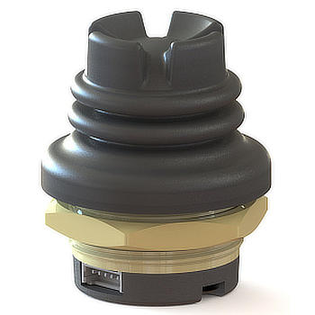
Ruffy TS1 Joystick

Thumb joysticks

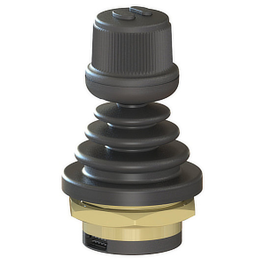
Thumb controllers are low-profile based joysticks that provide precise control with a variety of mounting and actuator options for ease of integration. Ultra MSI manufacture the 462 series and Ruffy Controls manufacture the TS1 series that are both perfect joysticks for applications such as Cursor Control, Target Acquisition, Security Cameras, Robotics and Automated Surgical Equipment.
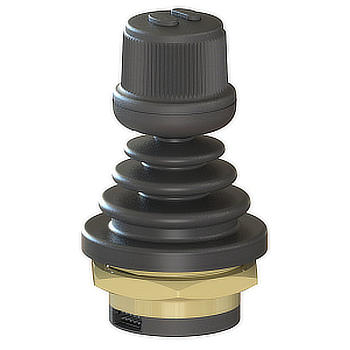
Ruffy HE1 Joystick

Finger joysticks

Finger joysticks are mainly used to provide control of movement and speed in low-profile units such as wheelchairs, medical instruments, robotic operations, and applications where precision and compact size are needed and the HE1 series from Ruffy Controls is just that, offering high precision within a compact panel mounted design.
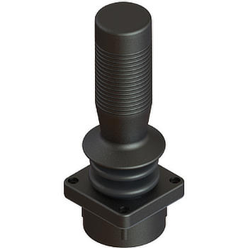
Ruffy SG Joystick

Hand Grip joysticks

Hand grip joysticks are widely used in heavy-duty applications such as mobile cranes, forklift vehicles, construction machinery, robotic machines, and agricultural equipment. Thanks to their sophisticated wear-free hall effect sensors and control mechanisms, these types of joysticks are highly versatile in multiple applications as is the SG series from Ruffy Controls which is a hall effect hand grip joystick with a redundant sensor, providing an extra level of safety making it the perfect choice for applications such as Remotely Operated Equipment and Automation Systems.

How do joysticks work?

A joystick is an input device consisting of a stick that pivots on a base and reports its angle and direction to the device it is controlling. It detects the direction of the stick by use of an electronic switch, Hall Effect, strain gauge or potentiometers.

What is a joystick?

A joystick is an input device which transforms mechanical movement from an operator and turns this into an electrical output and can control a computer game or machinery.

What are the types of joysticks?

There are several types of joysticks that most of us may be familiar with as they are used on game consoles and gaming computers, but the industrial joystick types are, thumb joysticks, finger Joysticks and handgrip joysticks.

What are joysticks used for?

Joysticks are widely used to control, steer, and position a wide range of heavy-duty equipment, machines, and systems such as agricultural machinery, cranes, oil rigs, forklifts, large vehicles, excavators, military equipment, hoist devices. Other joysticks such as small precision joysticks are used to control security cameras, remotely operated equipment and automation systems.

What is a hall effect joystick?

A hall effect joystick works in the same way to any other joystick but utilises the Hall Effect principle which allows the joystick to have a very long mechanical life due to there being no physical contact with the sensor and they can be designed to withstand excessive shock and vibration.

How does a potentiometer work?

In a joystick, a potentiometer is connected to each axis shafts so that pivoting the shaft rotates the contact arm. When the stick is moved there is a corresponding resistance change within the potentiometer. This adjusts the voltage, which can be interpreted by a computer programme as movement.

What is a strain gauge used for?

A strain gauge’s primary use is to measure force or strain. The resistance of a strain gauge changes when force is applied, and this change will give a different electrical output.

Contact our sales team today to discuss your joystick requirements. Contact Us
The Benefits of Fiber Laser Etching

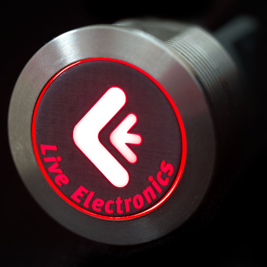
In this blog we will look at laser etching and laser engraving, the differences between the two and the benefits of each. Laser etching and engraving are additional services we can offer customers and this allows us to offer products marked with images such as company logos or product part numbers.

The name Laser is actually an acronym that stands for Light Amplification by the Stimulated Emission of Radiation. In the most basic terms this means they produce an intense light that when utilised correctly can disform, melt or even vaporise materials such as metals. Lasers therefore found a place within manufacturing and have been used since the early 1960s. Initially continuous laser beams were created that allowed for laser cutting and welding to take place, and continuous lasers are still seen in many industries today for cutting and welding processes. Later in the 1960s a technique called Q-switching was created, this allowed a laser to be turned on and off extremely rapidly to create a pulsed laser beam. These pulsed lasers made it possible for laser etching and engraving to occur. However, it wasn’t until the late 1990s that computer processing and software specifically designed for lasers was integrated into laser engraving machines giving rise to the capabilities that we see today.

While laser welding and cutting has been used for some time in manufacturing, laser etching transformed from initially being used as a gimmick to create artwork on wood and other materials such as leather to now being used intensively within industry to permanently mark products with information such as barcodes, logos, date codes and product codes. This also has a lot to do with recent industrial and government legislation that requires part identification and traceability, the benefits of using laser etching are the ideal solution to these new standards.

Difference between laser engraving and etching

There are a few differences between laser etching and laser engraving which are important to note. Each style uses a fiber laser and marks the material surface with an image, lettering or numbers however each go about this in different ways and give a different overall outcome.

All lasers work by emitting laser beams, however by utilising different specific wavelengths the operator can affect the outcome. For instance Co2 lasers used for welding and cutting use a wavelength of around 10,600nm whereas a fiber laser used for etching and engraving uses a wavelength of around 1,064nm. This lower wavelength effectively means the fiber laser generates more energy per pulse. This is important as the amount of energy per pulse used is what differentiates laser etching from laser engraving.

Laser etching works by altering the surface of the material, this is achieved by the laser delivering enough energy to a concentrated area of the surface to cause the material to melt and expand, when this area cools the surface roughness is changed creating a raised mark. Along with this slightly raised mark the surface is also discoloured and depending on how the operator has set the laser this can be black, white or grey in colour.

Engraving however requires an even more powerful laser or for the laser beam to pulse quicker resulting in a higher temperature. This is because engraving actually removes the surface material resulting in a cut or hole within the surface. This happens by heating the surface area to the point at which it vaporises. To produce a deeper engraving a laser may need several passes over the same area. This is why engraving takes longer to complete when compared with etching and results in only black markings. It is possible for a mix of laser engraving and laser etching to be used, this is a slower process but can result in the creation of very high contrast markings.

It would be remis at this point not to mention another type of laser marking, this is simply known as laser marking or laser annealing. This uses a laser beam that works at a lower temperature and moves slowly across the material surface in a method called discolouration. This option can create high contrast marks in different colours and does not damage the surface, however it takes a longer time to complete and can only be used on Steel, Stainless Steel and Titanium.

Benefits of Laser Etching and Engraving

The primary benefits of laser etching and engraving over other types of machined marking are due to there being no physical contact between the laser and the product meaning tool wear is no longer an issue and replacement tooling is not required, thereby cutting down on the longer term costs of marking products. Laser etching also allows for more intricate patterns to be created whether these be images, barcodes or written information and it offers better contrast over machined markings. Laser engraving can also offer deeper cut engravings which are more resistant to abrasion and are quicker to produce when compared to machine engraving saving on production time. Laser operating is also considered safer than machine marking for the operators.

As mentioned above the benefit of laser engraving over laser etching is that the markings are cut into the surface this means engraved markings are more resistant to abrasion. However, laser etching offers a higher contrast marking and can be created in black, white or grey compared with engraving which has less contrast and can only create black markings. This is why laser etching is predominantly used over laser engraving for the majority of products.

Laser etching FAQs

What is Laser Etching?

Laser etching is the process of marking materials such as metals, plastics, wood or leather with images, letters or numbers for product identification, traceability or purely aesthetic reasons.

How is laser etching done?

Laser etching is done by using a fiber laser machine that creates a specific wavelength beam of light to alter the surface of a material to produce an accurate representation of images, letters and numbers from a computer file.

Does laser etching wear off?

Laser etching creates a permanent change to the surface of the material. However, if the surface is subjected to severe abrasion the etching can wear away as the surface material is removed. It is better to use laser engraving for products that will be subjected to high abrasion as this is more resistant.

What is the difference between laser engraving and etching?

Laser etching and engraving both change the surface of a material. Laser etching produces a raised and coloured image that can be black, white or grey. Laser engraving on the other hand removes material from the surface creating a cut and due to this can only produce black coloured markings.

Is laser etching permanent?

Yes laser etching changes the surface of a material and therefore creates a permanent mark.

What materials can a fiber laser engrave?

A fiber laser is extremely adaptable and can be used to engrave many materials from metals such as Aluminium, Lead, Brass, Copper, Steel, Stainless Steel and Tungsten through to Ceramics, Carbon Fibre, Plastics, Glass, Wood and Leather.

For more information on our laser etching, engraving or marking capabilities contact our sales team here. Contact Us

IDEC’s Smart RFID Reader

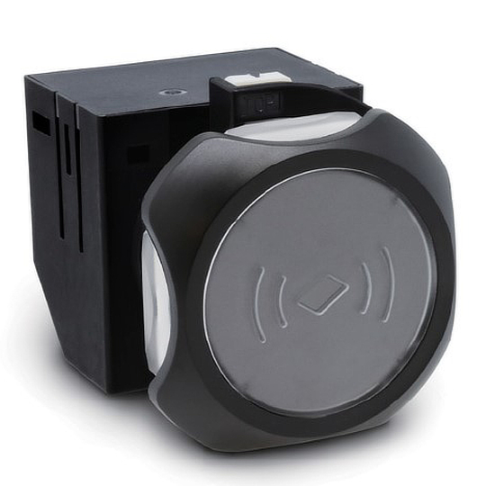
Are you wanting to make your production sites safer, keep track of who is entering and exiting your site and which employees are accessing equipment and machinery? Then look no further, IDEC have recently launched their Smart RFID Reader which has been designed to manage user authority for machines and equipment as well as controlling and tracking access to production sites. The RFID Reader is an ideal solution for applications such machine tool control units, automotive production, access control, food and packaging production and factory automation.

KW2D Unit

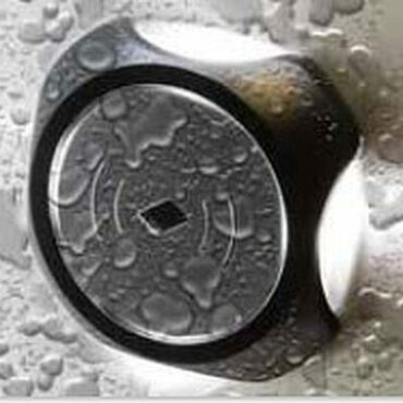
The RFID Reader provides a compact, smart and stylish design offering a panel cut out size of 22mm that can be IP65 or IP67 rated to protect from washdowns and oil spills. It is equipped with 4 LED indicators and an auxiliary buzzer to show when access has been granted or when there is an error and access cannot be granted.

The RFID Reader provides the utmost safety to production sites because employee ID cards are used to access the sites and the data from the ID cards is recorded on a host device to track entry/exit helping reduce the chance of unnecessary accidents if used correctly. It also logs the number of employees on the production site so they can all be accounted for and located quickly in the event of a fire or any other emergency.

The RFID Reader can limit access to equipment and machinery allowing only certain employees access which reduces the risk of equipment and machinery being misused or tampered with. Details of inspections carried out on equipment and machinery are also recorded electronically which reduces the need for paper or user input records which can be inaccurate or misplaced.

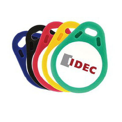
KW2D tags

The RFID reader has a range of accessories that are available including:

  • Available with or without a key fob tag holder
  • Key fobs available in 5 different colours
  • ID cards available in white
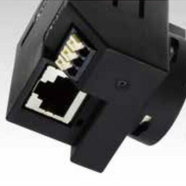
KW2D Ethernet

An Ethernet port enhances connection compatibility with host devices to reduce the possibility of loss of signal resulting in inaccurate or no data being recorded. Self-diagnostics are also carried out to check the memory status every time the product is switched on for added reliability. This makes the RFID Reader an ideal product for managing the mode of safe operation as specified in the ISO16090.

Don't delay contact us today! Contact Us

What is the difference between a Rotary Switch, Encoder and Coded Switch?

Introduction to Rotary Switches, Encoders and Coded Switches

In this month’s blog we are going to look at what Rotary Switch, Rotary Encoder and Coded Switches are, how they work, their benefits and what the difference is between each one.

What are Rotary Switches?

A Rotary Switch is operated by the rotation of an actuator, they are often chosen when 2 or more positions are needed to select different electrical circuits within a device. Rotary Switches can stop in several positions to control multiple circuits with a single switch. They are normally available with a choice of shorting (make before break) or non-shorting (break before make) contacts.

The advantages of Rotary Switches are they can control numerous circuits without the need for multiple switches as they can be designed with numerous contact points. Rotary switches are commonly used in applications including CB radios, industrial controls, electronic instruments and even aircraft, although they are less common than they used to be. Rotary Switches can also be designed with a detent mechanism so they “click” and hold from one active position to another rather than stalling in an intermediate position.

Dailywell RT2 Series, Rotary Switch

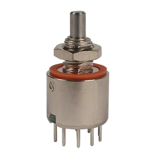
Live Electronics works with Dailywell, Idec, Lorlin and Elma, who between them manufacture a vast range of Rotary Switches. Elma also make precision versions of Rotary Switches. Dailywell manufacture the RT2 Series that are designed as single pole switches with between 2 and 8 positions with off in the extreme anti-clockwise position and between 45° to 360° travel depending on the number of positions. They have a mechanical life of 10,000 cycles. The RT2 series is perfect for applications such as Telecommunication Equipment, Computer Peripherals, Networking Systems and Audio-Video Equipment.

Elma, MR50, Without Knobs

Elma specialise in manufacturing precision Rotaries, including the highly reliable and rugged MR50 Rotary Switch which has a miniature body of just ½ an inch in diameter and is sealed to IP68. The switch is available in 10, 12 and 16 positions. It has a minimum mechanical life of 20,000 cycles. The internal contacts are also gold plated to ensure reliable switching at low voltages. Due to its robust nature and operating temperatures of -45°C to +85°C the MR50 is perfect for demanding applications including Two Way Radios, Medical and Testing Equipment, Military Targeting Devices and Night Vision Devices.

What are Rotary Encoder Switches?

Rotary Encoders are devices that convert the rotational movement of the shaft into an analogue or digital signal. This is done by converting an input voltage into a different output voltage (analogue) or a digital signal depending on the position of the shaft. It provides information on position, speed, count or direction. They Key benefit of using a Rotary Encoder Switch is that it can rotate in the same direction indefinitely. Due to their robustness and fine digital control; they are used in many applications including robotics, CNC machines and printers. Rotary Encoder Switches measure rotary movements and displacement and can either be absolute or incremental which we will explain below.

Within an Absolute Encoder Switch, the position is retained regardless of whether the encoder is powered or not, even if a movement is made without power to the encoder, the encoder still knows the true position. These can either be single turn or multi-turn, whereby the requirement is to know not only the position over one turn of the shaft but how many turns have been made in total. Multi-turn encoders are suited to applications where complex or lengthy positioning measurements are involved. Single-turn encoders are more suited to short travel applications where position measurement is required within a single turn of the encoder.

There are several advantages to the Absolute Encoder and these are as follows; their true position is not lost if there is a loss of power, continuous reading of a position is not required, and they provide high resolution up to 16 bit single and 44-bit multi-turn.

An Incremental Encoder Switch works by transforming the angular position of the shaft into digital or pulse signals by means of an optical disk. A certain number of pulses are generated per revolution and each pulse is an increment corresponding to the defined resolution. An Incremental Encoder can measure the change in position but not the absolute position.

Every time an Incremental Encoder is switched on the pulse is counted from zero, this means that the position is not stored and a ‘reset or reference’ position must be obtained before the encoder begins counting again. This is the main difference between an absolute and an incremental encoder.

The advantages of Incremental Encoder Switches are, they are more cost effective and less complex compared to an Absolute Encoder Switch and they can determine speed and direction.

What are Rotary Coded Switches?

A Rotary Coded Switch is used to select one of several options. This device is like a rotary switch, except the outputs are binary encoded to reduce the number of terminations required. Rotary Coded Switches are activated by a rotating shaft and have several positions. They are mounted on printed circuit boards (PCBs) in order to control their output. Some Rotary Coded Switches are actuated with a screwdriver, others include thumbwheels or push wheels that are turned manually. They can be designed either to rotate continuously through 360 degrees, or to stop at pre-set positions as they turn.

Rotary Coded Switches have many advantages which include their mechanical life, number of positions, they can rotate 360 degrees or stop at pre-set positions as they rotate, and they can be used in applications including Two Way Radio Devices, Target Aiming Devices, Aircraft Transponders, Medical Equipment and Industrial Automation Equipment.

Dailywell, RSC Series Coded Rotary Switch

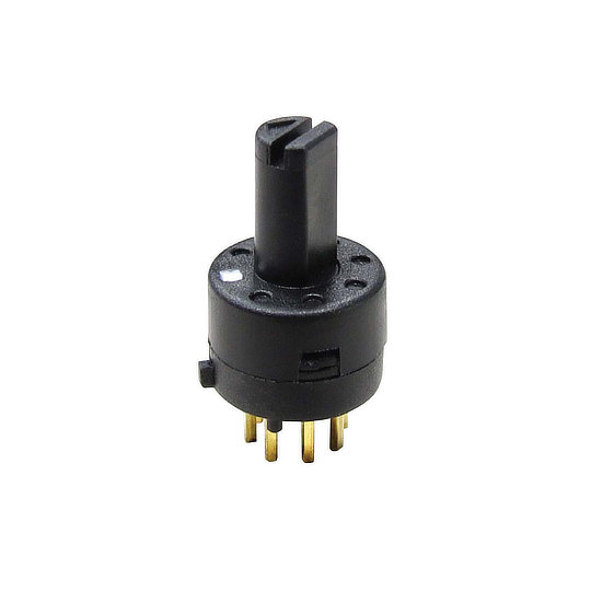
Dailywell and Elma manufacture Rotary Coded Switches. Dailywell manufactures the single pole RSC series Rotary Coded Switch with 4, 10, or 16 positions through 360 degrees. They are available with real or complementary code and have a mechanical life of 10,000 cycles. The RSC series are ideal for applications such as Telecommunication Equipment, Computer Peripherals, Networking Systems and Audio-Video Equipment.

What is the difference between a Rotary Switch, Encoder and Coded Switch?

While all are activated by a rotating shaft the differences are that a Rotary Switch selects different electrical circuits within a device. An Encoder Switch converts the rotational movement of the shaft into an analogue or digital signal, while a Coded Switch uses binary coded outputs to reduce the number of pins required.

The advantage of using a Rotary Switch over a Rotary Encoder Switch is having several positions to control many different circuits with a single switch. They are used in many applications including CB radios, industrial controls, electronic instruments and aircraft. The advantages Rotary Encoder Switches have over Rotary Switches include being able to convert the rotational movement of the shaft into an analogue or digital signal and it provides information on position, speed, count or direction.

The advantages of using a Rotary Switch over a Rotary Coded Switch include being able to control many different circuits with a single switch. The advantages Rotary Coded Switches have over Rotary Switches include the reduction in the number of pins due to the output being binary encoded and they are available with real or complementary code.

The advantages Rotary Encoder Switches have over Rotary Coded Switches include converting the rotational movement of the shaft into an analogue or digital signal and they provide information on position, speed, count or direction. Rotary Coded Switches advantage over Rotary Encoder Switches is having the option for several distinct positions.

Additional Information

Binary-Coded Decimal

Binary-Coded Decimal is a class of decimal numbers where each digit is represented by a fixed number of bits, usually four or eight. Sometimes, special bit patterns are used for a sign or other indications (e.g., error or overflow).

Hexadecimal Code

The Hexadecimal, or Hex, numbering system is commonly used to reduce large strings of binary numbers into a set of four digits for us to easily understand. Hexadecimal numbering system uses 16 different digits, a combination of 0-9 & A-F and are a popular choice for representing long binary values because their format is compact.

Gray Code

Gray Code or Reflected Binary Code (RBC) is ordering of the binary numeral system such that two values differ in only one bit for example the representation of the decimal value “1” in binary would normally be “001” and “2” would be “010”. In Gray code, these values are represented as “001” and “011”. That way, incrementing a value from 1 to 2 requires only one bit to change, instead of two.

Gray Code is widely used to prevent false output from electromechanical switches and to facilitate error correction in digital communications such as digital terrestrial television and some cable TV systems.

FAQ’s

How do Rotary Switches work?

Rotary Switches are operated by rotation and can stop in several positions to control many different circuits with a single switch.

How to install a Rotary Switch?

Most Rotary Switches are PCB mount and installation will all depend on the boards design. If you are manually installing a Rotary Switch you will need to prepare your wires and connect the supply wire to the supply (common) terminal, usually found in the centre of the switch terminations, and connect the remaining wires to the different contacts in relation to the circuit they are switching.

What is a Rotary Switch?

A Rotary Switch is operated by rotation, they are often chosen when 2 or more positions are needed to select different electrical circuits within a device.

What is a Rotary Switch used for?

A Rotary Switch is used for many applications including CB radios, industrial controls, electronic instruments and even aircraft.

What is a Coded Rotary Switch?

A Rotary Coded Switch is used to select one of several options. This device is like a rotary switch, except the outputs are binary encoded to save on pin requirements.

What is a Rotary Encoder Switch?

Rotary Encoders are devices that convert the rotational movement of the shaft into an analogue or digital signal. They provide information on position, speed, count or direction.

How does a Rotary Encoder Switch work?

A Rotary Encoder Switch produces either analogue or digital signal, according to the rotational movement.

What is the function of a Rotary Encoder Switch?

A Rotary Encoder Switch detects rotation angle or linear displacement. Encoders Switches are used in devices that need to operate in high speed and with high accuracy.

Contact our sales team today to discuss your switch requirements! Contact Us

The Hall Effect: Explained

Introduction to Hall Effect

In this blog we are going to discuss the science of Hall Effect, how it works, why the effect is important, what products the effect is used in and what the advantages are.

What is the Hall Effect?

Hall Effect is named after American physicist Edwin H. Hall who first introduced the theory to the world in 1879 when he was doctoral candidate at Johns Hopkins University in Baltimore. Hall discovered that when a conductor or semiconductor with current flowing in one direction was introduced to a perpendicular magnetic field a voltage could be measured at right angles to the current path, this measurable voltage is the Hall Effect.

How does it work?

The Hall Effect takes place when you set current flowing through a conductor which is a material such as copper or silver that permits electrons to flow freely across the entire surface area. The electrons begin to flow in a straight line from one side of the conductor to the other. If you were to then introduce a magnetic field near the conductor, it would disturb the flow of the electrons due to the force applied. This is called Lorentz Force, which is the force on a charged particle due to electric and magnetic fields.

The magnet’s north pole pulls the negative electrons to one side of the conductor and deflects the positive electrons to the other side of the conductor. If you then put a voltage tester between the two sides you will be given a voltage reading because there is current between the positive and negative electrons, by retrieving this measurable voltage you are putting the Hall Effect principle into practice. In a semiconductor such as silicon or germanium, the drift velocity of electrons is a lot quicker due to the material used. This results in a stronger Hall Effect which corresponds to a larger voltage reading being detected and therefore a more precise reading taken.

Hall Effect Products

Hall Effect is used in several different products such as sensors, joysticks and switches. We will now discuss the different products to understand what they are, their benefits and their applications. At Live Electronics we work with several manufacturers that produce Hall Effect products, we will also discuss the different manufacturers and their products.

ZF, Speed and Direction Sensor

Hall Effect Sensors

A Hall Effect sensor is a device to measure the magnitude of a magnetic field. Its output voltage is directly proportional to the magnetic field strength through it. Hall Effect sensors are used for proximity sensing, positioning, speed detection, and current sensing applications. Other sensors include the Inductive sensor which is a non-contact electronic proximity sensor. It is used for positioning and detection of metal objects.

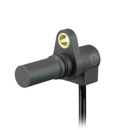
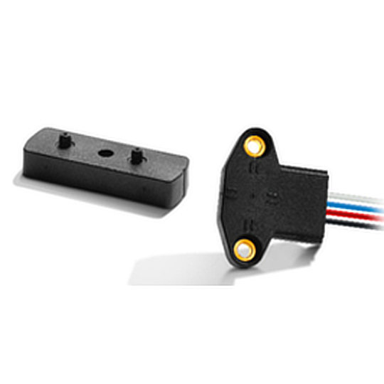
Live Electronics work with ZF Electronics who manufacture Hall Effect sensor such as the SD74/SD84/SDB4 series of Gear-tooth speed and direction sensors that are designed with two internal hall effect cells, together they can be used to detect both the speed and direction of movement of a gear. By using two Hall Effect magnetic field cells placed near to the gear-teeth of the gear that is to be measured, the movement of the gear tooth passing the magnets disrupts the magnetic field. This disruption is picked up by the sensor and the output signal can be used to calculate the gear’s speed and direction of movement. The SD74/SD84/SDB4 series has several benefits which include being IP67 rated, immune to vibration, shock, and dirt for improved functional safety. The ideal applications are Automation Systems, Conveyors and Wind Turbines.

ZF, LIN Sensor

ZF Electronics also provide Linear Positions Sensors. Their LIN series are contactless hall effect sensors offering linear voltage output and a long mechanical life. The sensor has dual independent outputs with redundancy to offer the most reliable and accurate sensor possible. The benefits of the LIN series include being IP68 rated, robust and reliable. The LIN series is designed for many applications such as gear selection, hydraulic controls and steering wheel positioning.

Hall Effect Joysticks

Hall Effect joysticks are devices that use non-contact sensors to change the physical movement from an operator into an electrical signal which can be understood by a computer system. Hall Effect joysticks are extremely robust and have a very long mechanical life due to there being no psychical contact with the sensor. A Hall Effect joysticks mechanical life can range from 1 million cycles (also known as actuations) to 15 million cycles.

There are several types of joysticks being used today, one of them being the Potentiometer joystick. The Potentiometer joystick is a device that has been around for years and they contain several components that increase or decrease the level of resistance within the electronic circuit. Potentiometer joysticks do still offer great performance but in terms of long-term durability these joysticks may be susceptible to reliability issues due to the wearing of moving parts and minor vulnerability to electromagnetic interference or radio frequency interference. As mentioned previously, Hall Effect joysticks have a very long mechanical life due to there being no physical contact with the sensor and they are designed to withstand excessive shock or vibration giving them an advantage over the Potentiometer joystick.

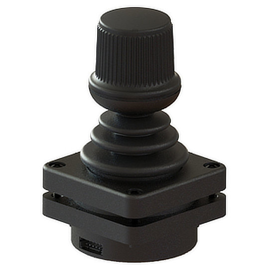
Live Electronics work with a joystick manufacturer, Ruffy Controls. They have a large portfolio of joysticks, several of them being Hall Effect. The HE3 series from Ruffy Controls is a Hall Effect joystick that is designed with built in redundant sensors to provide an extra level of safety. Ruffy Controls joysticks can be designed specifically to meet customer needs and the HE3 series is no different. The HE3 series are available in 2 or 3 axis, provide options for push buttons on the joystick handle, a choice of limiters (square, guided feel, round limiter), the output voltage you require and they are available in different colours. The benefits of the HE3 series include being IP67 rated, extremely rugged, a mechanical life of 5 million actuations in all directions and excellent return to value. The HE3 series are the perfect joysticks for applications such as industrial machinery, agricultural machinery, CCTV control systems and automation systems.

Ruffy, Ruffy Controls, HE3 Joystick

Hall Effect Switches

Hall Effect switches are devices that turn on in the presence of a magnetic field and turn off when the magnet is removed. They are designed with contactless sensing to ensure maximum ruggedness, reliability and mechanical life.

There are several different style switches available one of them being a pushbutton switch. A pushbutton switch requires downward pressure to be applied to activate or deactivate a circuit. They provide an on-off functionality, but different variants are available. Their switching action can be maintained (staying in one position after pressure has been applied) or momentary (returning to their original position once pressure is removed). Due to electromechanical Pushbuttons requiring physical pressure to be applied to function, they experience a lot of physical wear and tear resulting in a shorter mechanical life of around 50 thousand cycles. Physical contact is largely reduced with a Hall Effect switch due to them having contactless sensing, which gives them a much longer mechanical life of around 1 million to 15 million cycles.

Elma, Multi Rotary Switch, Hall Effect, Coded Switch, Incremental Encoder Switch

Hall Effect Rotary Switches

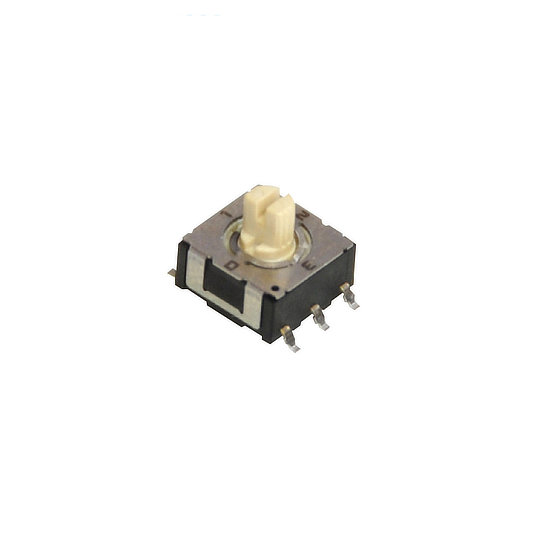
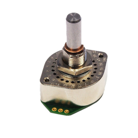
We work with Elma Electronics Ltd who manufacture the X4 series which is a high-performance Hall Effect multi rotary switch. A rotary switch is a switch operated by rotation. They are often chosen when more than 2 positions are required. The X4 series from Elma is an extremely robust and rugged switch with a mechanical life cycle of 1 million rotations. It provides an IP67 rating with a stainless-steel shaft making the switch robust and rugged. There are many applications the X4 series can be used in and examples are construction, transportation controls, machine tools and plant construction.

Advantages of Hall Effect

Hall Effect devices have many advantages, they are immune to dust, dirt and water and due to their frictionless operation, they have extremely long mechanical lives. They are robust, rugged and can withstand intense vibration and shock. Hall Effect devices can offer high speed operation and they can operate in a wide temperature range.

FAQ's

What is Hall Effect?

Hall Effect principle is when a current is passed in one direction through a conductor and a magnetic force is introduced perpendicular to this, the magnetic field moves the electronics within the conductor creating a voltage change. You can then measure the change in voltage by taking a voltage reading at right angles to the currents path, this measurable voltage is the Hall Effect.

What is a Hall Effect sensor?

A Hall Effect sensor is a device that measures the magnitude of a magnetic field. Its output voltage is directly proportional to the magnetic field strength through it.

What is a Hall Effect joystick?

Hall Effect joysticks are devices that use non-contact sensors to change the physical movement from an operator into an electrical signal which can be understood by a computer system.

What causes Hall Effect?

The Hall Effect is the movement of electrons through a conductor towards a magnetic attraction. It causes a measurable voltage differential across the conductor such that one side is positively charged and the other negatively.

What is the use of a Hall Effect sensor?

Hall Effect sensors are used for proximity sensing, positioning, speed detection, and current sensing.

How accurate are Hall Effect sensors?

Hall Effect sensors can achieve output error as low as 1%.

Contact our sales team today to discuss your requirements! Contact us

D-Sub Connectors – All you need to know

D-Sub Connectors

The D-subminiature connector, more commonly known as a D-Sub connector is a family of connectors that were introduced by Cannon in 1952 and they are still being widely used today. Although in today’s electronic marketplace technology is ever-changing and adapting to meet consumer wants and needs. Despite being over 60 years old, there are still plenty of devices using D-Sub technology that we are still reliant on. In this article, we are going to discuss what D-subs are, where they are commonly used, what they look like and their importance in today’s modern world.

What is a D-Sub Connector?

The D-sub is one of the most popular electronic connectors in the world, with many types, sizes, and applications. It is a very versatile type of electrical connector. These compact connectors take their name from their characteristic D-shaped shield. D-subs establish a connection between two points to facilitate the transfer of information or power.

D-subs were used for monitors and disk drives, now they are used for industrial and military networking, sensors and in areas where electromagnetic interference can be an issue to the device or the to the environment.

D-sub is the name given to a family of connectors, and several connectors that make up the family are Combi D-Sub Connectors, Dual-Port D-Sub Connectors, Filtered D-Sub Connectors, High-Density D-Sub Connectors, Standard D-Sub Connectors and D-Sub Hoods which will now be explained in further detail.

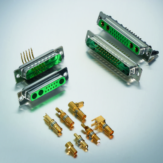
Combi D-Sub Connectors are a hybrid connector featuring different connector styles within a D-Sub housing. This allows designers the ability to have a mix of different contacts within a single D-Sub whether these be signal, high current, high voltage, coaxial or pneumatic. Deltron AG, a Swiss manufacturer of high-end D-subs have 24 standard styles to choose from each offering distinct features within 5 different housing sizes. The number of contacts range from 2-43. Terminations can be either solder pin, press-fit or solder cup. The power contacts can be 10A, 20A, 30A or 40A and can be requested with sealing up to IP68.

To understand more about IP rating please see the blog on our website which explains it in more detail here.

Dual-Port D-Sub Connectors are designed for applications that require multiple connector ports with limited “PCB” space, through the stacking of two 90° D-Sub connectors, one on top of the other. Dual Port D-Subs are available in various designs with numerous assemblies and the number contacts range from 9-37.

Deltron AG, Deltron, Filtered D-Sub Connectors, Filtered D-Subminiature, Filtered D-Sub

Filtered D-Sub Connectors have a very good filter quality to protect against Electromagnetic Interference. The Planar Filter Connectors (FP) and the PI Filter Connectors from Deltron AG are specially developed for industrial applications and offer excellent protection against Electromagnetic Interference (EMI) and Radio Frequency Interference (RFI) which can be caused by lightening, solar magnetic storms, radio signals, mobile phones, electronic motors, computers, medical equipment and power lines.

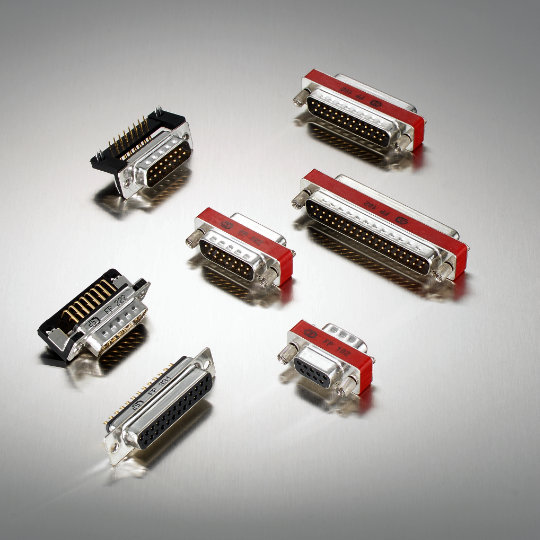
Standard D-Sub Connectors are high quality and robust connectors designed for the most demanding applications. They are available with different assembly parts for mounting, for example, crimp assembled,  press-fit assembled, solder cup assembled, or 90° angled solder pin.

Deltron AG, High-Density D-Sub, D-sub Connectors

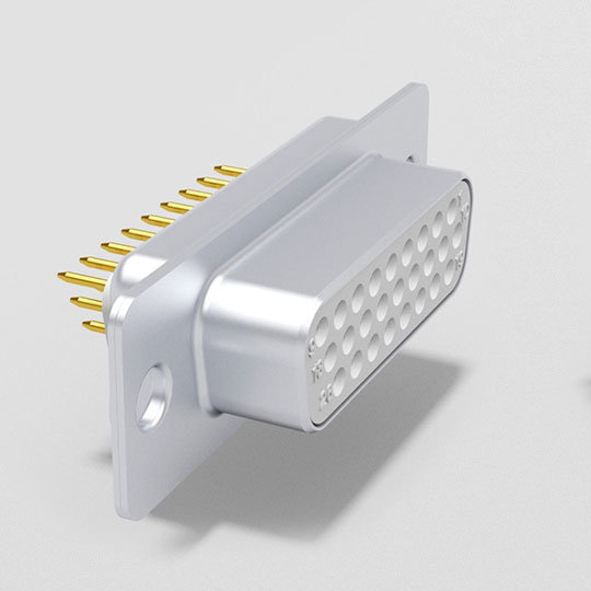
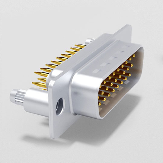
High-Density D-Sub Connectors are designed for applications which require the best possible contact density. Due to the high density of the 15, 26, 44, 62 and 78 contacts, this series is ideal for the most modern applications. A very common high-density connector is the Video Graphics Array (VGA) connector which is a 3 row 15 pin connector used in computers.

D-Sub Hoods are designed to perfectly match Deltron AG’s range of high-quality D-Sub connectors. They are available in 9, 15, 25, 37 or 50 pin versions. The D-Sub Hoods provide optimum protection to the connector to prevent damage.

What does a D-Sub Connector look like?

They are shaped like the letter “D,” with one side slightly longer than the other. Due to the shape, there is only one way to connect a device. All D-Sub connectors have a metal housing that surrounds two or more rows of male or female contacts. Inside the housing, the contacts are aligned to match the equivalent pins or sockets in the mating half of the connector. The contacts are generally gold-plated copper alloy, and they are surrounded by a layer of insulation made from a variety of materials, including glass-filled thermoplastic, a common insulating plastic.

All the Deltron AG D-Subs discussed above have contacts that are finished in a hard gold plate over nickel and they are available in different quality classes (QC).  For example, QC1 is capable of 500 mating cycles or QC2 which is capable of 200 mating cycles.

What is a D-Sub Connector used for?

D-Subs were once heavily used in home computing, printer cables, computer game controllers, external floppy disk drives, network ports and multi-channel audio recording systems but technology has advanced the need for D-subs has decreased in these areas. As previously mentioned, they are now predominantly used in industrial, aerospace, military, transportation and medical diagnostics because they are extremely rugged, small enough to fit into tight spaces, have a very long-life cycle and can withstand being exposed to harsh environments.

Due to their ability to be created in multiple variations, be environmentally sealed & locked and have EMI filtering, D-Subs are used in many industries such as aerospace, military, industrial, transportation and medical. They are commonly used in critical applications such as helicopters, combat aircraft, high-speed rail, patient monitors, ultrasound and MRI imaging.

What are the advantages and disadvantages of a D-Sub Connector?

As modern technology is forever changing and constantly becoming more lightweight and sleeker, D-Subs are being utilised less on modern devices like laptops, monitors and televisions where physical depth and weight are important to the user. D-Sub connectors take much longer to plug in and unplug due to their size and termination, unlike USB and HDMI connectors.

The advantages of D-Sub Connectors are they are extremely rugged and can be used in harsh environments. They are small enough to fit into tight spaces and have a long-life cycle. They are diverse and work well within many different industries as we have discussed throughout. D-Subs are well suited for locking technology which means that hardware keeps the plug and socket components in the mated position, they have several different terminations e.g., solder, screw and crimp meaning they offer better resistance to tampering as well as jostling. As can be seen, the D-sub technology may not be the most up to date solution but remains the best solution in many different environments.

If there is anything we can help you with please contact us with your enquiry Contact Us